The experimental stream reclaimer is presented schematically in Figure 1. This reclaimer is characterised by a very simple structure, providing a possibility of applying more crushing elements (in vertical direction), which increases the yield of the reclamation process, of mainly continuous character. In addition, an application of feeders allows a precise control of the amount of the introduced spent moulding sand. This reclaimer enables a proper separation of the reclaimed moulding sand from a dust-air mixture, and the obtained - of full value - raw material can be reused in the moulding sands preparation.
Rysunek 1 przedstawia widok doświadczalnego regeneratora mechanicznego RD-6
z pyłomierzem tryboelektrycznym PM 103 do monitoringu koncentracji pyłów
w układzie odpylania.
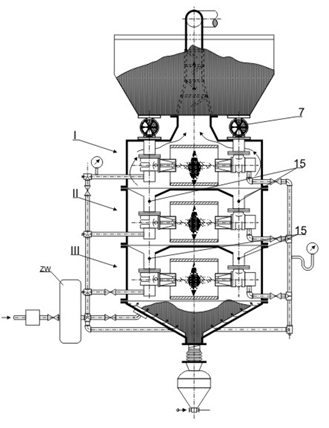
Fig.1. Schematic presentation of the experimental stream reclaimer, 1- Charge tank, I, II, III - Crushing element, 2 - Casing, 3 - Pneumatic jet pump, 4 - Exhaust nozzle, 5 - Collision zone, 6 - Abrasive screen, 7 - Feeder, 8 - Dumping hopper, 9 - Perforated floor, 10 - Compressed air installation, 11 - Compressed air conduit, 12 - Dedusting installation, 13 - Cascade classifier, 14 –Receiver, 15 - Delivery channel